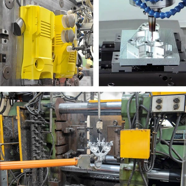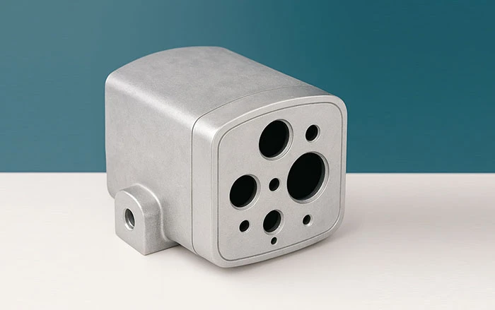
For smart home cameras, ADC12 die-cast aluminum housings have become the mainstream choice for mid- to high-end models thanks to their high mechanical strength (tensile strength approx. 220 MPa) and excellent heat dissipation (thermal conductivity around 100 W/(m·K)). However, from design to mass production, engineers must address several core challenges, including non-uniform wall thickness, insufficient structural rigidity, difficult demoulding, and inadequate dimensional accuracy. This article focuses on four critical aspects — wall thickness design, stiffening rib layout, demoulding optimization, and the necessity of CNC finish machining — and provides practical design methods and production guidelines to support successful project implementation.
1. Wall Thickness Design: Balancing Strength, Thermal Management, and Castability
Wall thickness is the foundation of aluminum housing design. It directly affects the filling, structural strength, and thermal performance. The design must avoid two typical pain points: “too thin causing poor filling” and “too thick causing shrinkage porosity”.
Design Guidelines
- Typical range: For ADC12 die-castings, a recommended wall thickness is 2–4 mm (2.5–3 mm is commonly used for camera housings). Fragile walls (< 1.5 mm) make molten metal flow difficult, leading to cold shuts and short shots; excessively thick walls (> 5 mm) cause uneven solidification, resulting in shrinkage porosity and gas pores that reduce structural strength. In customer feedback, “plastic parts deforming under high temperature” is a frequent pain point; for aluminum housings, properly controlled wall thickness ensures heat dissipation — the thinner the aluminum wall, the larger the heat transfer area and the better the heat dissipation for the PCB and image sensor.
- Differentiated design: Load-bearing areas (such as the lens mount boss and screw bosses) can be locally thickened to 3–4 mm (for example, the area around the lens opening that supports the lens weight is ideally 3.5 mm); non-load-bearing areas (such as housing edges) can be reduced to 2 mm to balance weight reduction and material cost. In a typical structure, a 2 mm wall thickness compared with 3 mm can achieve roughly 15% weight reduction and around 8% savings in raw material costs, subject to verification against the actual part geometry.
Common Issues and Solutions
- Issue: Non-uniform wall thickness leads to warpage due to differential cooling and solidification (for example, front cover warping affects lens alignment; many “misaligned assembly” complaints from end users can be traced back to this).
- Solution: Use a “gradual transition” design with a wall thickness change ratio ≤ 1:3 (e.g., when transitioning from 3 mm to 2 mm, the transition length should be ≥ 3 mm). Add process grooves at sudden transitions (typical width 5 mm, depth 0.5 mm) to relieve stress. This approach can effectively reduce distortion (specific values should be confirmed by testing on the actual product).
2. Stiffening Rib Layout: Improving Rigidity and Avoiding Fracture Risk
Although ADC12 aluminum alloy has a tensile strength of about 220 MPa (compared with roughly 40 MPa for ABS plastic), a thin and slender structure can still fracture during drop impact. Rib design must balance stiffness improvement and die-casting feasibility.
Design Guidelines
- Dimensional rules: Rib thickness should be ≤ 2/3 of the adjacent wall thickness (for a 3 mm wall, ribs are typically 1.5–2 mm); rib height should be ≤ 5 times the wall thickness (≤ 15 mm) to avoid “hot spots” (regions of slow solidification that create porosity). Field feedback shows that many “outdoor drop fracture” failures originate from shrinkage porosity at rib intersections, which must be carefully handled in the design.
- Layout principles: Arrange longitudinal ribs along the main load direction (such as around mounting brackets). Use grid ribs (20–30 mm spacing) on large flat areas (e.g., rear cover) to improve resistance to bending and deformation. Use generous fillets at rib roots (R0.5–1 mm) to avoid stress concentrations; this fillet design can significantly reduce fracture risk during drop tests.
Common Issues and Solutions
- Issue: At cross-shaped rib intersections, the effective wall thickness becomes excessive (e.g., up to 4 mm), causing internal shrinkage porosity after die casting, leading to fracture during a 1.5 m drop test.
- Solution: Add process holes at intersections (typically 3–5 mm diameter) or stagger the ribs (offset by about 0.5 mm) to reduce local wall thickness. Provide a 0.5 mm draft angle at rib tops to facilitate demoulding.
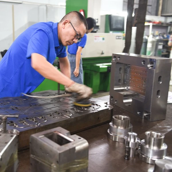
3. Demoulding Optimization: Ensuring Productivity and Reducing Tooling Wear
Die-casting molds are expensive (a single-cavity tool typically costs around RMB 90,000–140,000). Poor demoulding design can lead to high ejection force, part scratching, and low yield, which directly affect mass-production efficiency.
Design Guidelines
- Draft angle and surface roughness: Provide a draft angle of 1–2° on external walls and 2–3° on internal walls (deep cavities such as lens bores should use about 3°) to ensure smooth ejection. Recommended surface roughness is Ra 1.6–3.2 μm (slightly higher than that of plastic housings) to reduce sticking and galling. Production feedback shows that increasing the external draft from 1° to 1.5° significantly reduces demoulding force and extends tool life.
- Fillets and undercuts: All corners should have R0.5–1 mm fillets. Sharp-corner designs typically yield only about 80,000 shots, whereas properly filleted designs can reach ~120,000 shots. For fastening features, screws are preferred over snap-fits requiring side cores; side-core and slider mechanisms can increase mold cost by 15–25%, so undercuts should be avoided unless necessary.
Common Issues and Solutions
- Issue: Internal walls without draft cause high ejection force and deformation during demoulding (local sinking or scuffing on inner sidewalls, sharply reducing yield).
- Solution: Enforce at least 2° draft on internal walls. For critical vertical surfaces such as lens bores, reserve 0.3 mm machining allowance for CNC finishing after die casting to restore perpendicularity and positional accuracy. With a proper process window, final assembly yield can be improved to over 99%.
4. CNC Finish Machining: Guaranteeing Accuracy of Critical Dimensions
The standard ADC12 die-casting dimensional tolerance is about ±0.3 mm, which is insufficient for smart camera precision requirements (lens bore coaxiality: ±0.05 mm; flatness: ≤ 0.1 mm). CNC finish machining is therefore necessary.
Design Guidelines
- Areas requiring machining: Lens bores (tolerance ±0.05 mm), screw boss holes (±0.1 mm) and reference mounting faces (flatness ≤ 0.1 mm). A machining allowance of 0.3–0.5 mm should be reserved to remove the cast surface layer and any subsurface porosity. An appropriate machining allowance significantly improves the capability for critical dimensions.
- Cost control: Non-mating areas (external cosmetic surfaces, decorative grooves, etc.) are finished directly by die casting without secondary machining. CNC machining accounts for roughly 5–12% of the unit cost per housing; for a batch of 100,000 units, this may be around RMB 1.8 per piece. Full-surface machining would increase the total cost by roughly 40%.
Common Issues and Solutions
- Issue: Casting distortion (e.g., flatness out of tolerance by 0.2 mm) leads to parts still failing after CNC machining.
- Solution: Apply “counter-deformation” (pre-deformation) in the mold design — pre-bend the cavity by 0.1–0.2 mm to compensate casting shrinkage and warpage, which effectively reduces deformation (trials must validate exact values). Use three-point location fixtures for CNC machining: first, machine the mounting faces (machine datum faces); then re-locate on these datums to machine the remaining critical dimensions.
Conclusion: Integrating Structure, Process, and Application Scenarios
For smart home camera housings made of ADC12 die-cast aluminum, design should follow core principles such as “wall thickness 2–4 mm (matched with an injection speed of 3–5 m/s), ribs sized at roughly two-thirds of wall thickness with 3–5 mm process holes at intersections, draft angles of 1–3°, and CNC finish machining for critical dimensions”, to balance structural strength, manufacturability and end-user requirements (such as outdoor impact resistance and high-temperature thermal management). However, die casting is more complex than plastic injection molding; a well-engineered design can deliver “military-grade weather resistance” and fully support the positioning of mid- to high-end innovative camera models.